Raymarching + Rasterization
First read this post on Syntopia’s blog.
The imaged-based worlds of Shadertoy
Shadertoy’s authors create entire lush worlds eschewing the entire graphics pipeline but the very last phase. Using image-based techniques like ray {tracing, casting and marching}, each pixel’s color is calculated from scratch every frame. This means the workflow is always divergent, and there is an inherent limit on the complexity a scene may contain. This has not kept the leading practitioners in the field from developing new techniques to stretch these limits or make more within them.
The good old raster pipeline
But there’s all this pipeline architecture for doing rasterization of primitives and all kinds of performance benefits to be gained from culling and sorting them on the front end. Not to mention the millions(probably billions or more) of developer-hours invested in custom hardware design and drivers. To get the most out of your GPU, we should be using this stuff.
Combining the two
To render to a single image using both approaches to rendering, the viewing parameters must match exactly. The last two require some work to agree:
- View matrix
- Projection matrix
- Depth buffer
The view matrix is easy enough to match raster-raymarch. Most examples on Shadertoy use a {ro,rd} pair (which stands for Ray Origin, Ray Direction) which can both be simply transformed by a viewing matrix to position them in world space(or to position the world in eye space). Remember that ro.w == 1. and rd.w == 0., meaning that translation applies to ro but not to rd.
The projection matrix is a slightly more subtle thing. It encodes the Field of View(FOV), aspect ratio, and near and far clipping planes. The OVR SDK also uses it to encode stereo separation using an off-axis viewing frustum. This turns out to be very convenient. Thank you again OVR SDK developers for doing what seems to be the right thing here.
The depth buffer encodes each pixel/fragment’s depth from the camera and is used for occlusion testing. There are several clever ways in which fragment depth is encoded in the buffer that confer useful features and require some math to get correct. We can write to the depth buffer by assigning a value to the variable gl_FragDepth in a fragment shader and it will be used for occlusion in the next(raster) pass automatically by the graphics pipeline. Using the excellent Syntopia blog post as a guideline, we can encode the fragment depth into a value range usable by OpenGL.
float ndcDepth = ((zFar+zNear) + (2.0*zFar*zNear)/eyeHitZ)/(zFar-zNear);
float dep = ((gl_DepthRange.diff * ndcDepth) + gl_DepthRange.near + gl_DepthRange.far / 2.0;
We can obtain the zNear and zFar depth range values directly from our Projection matrix with some algebra. Using column-major matrix convention, the projection matrix looks like the below image(hotlinked without permission):
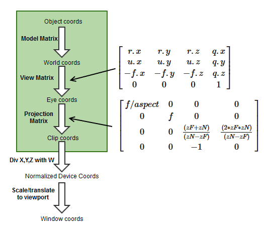
We extract the two matrix values containing zNear and zFar into p10 and p11 and do some algebra to express ndcDepth in terms of p10 and p11:
p10 = (zF+zN) / (zN-zF)
p11 = (2*zF*zN) / (zN-zF)
ndcDepth = [ (zF+zN) + (2*zF*zN)/eyeHitZ ] / (zF-zN)
Recognizing that (zF-zN) = -(zN-zF), we can extract a common denominator:
-1 * ndcDepth = [ (zF+zN) + (2*zF*zN)/eyeHitZ ] / (zN-zF)
ndcDepth = -[ (zF+zN) + (2*zF*zN)/eyeHitZ ] / (zN-zF)
Separating terms:
ndcDepth = -[ (zF+zN)/(zN-zF) + ((2*zF*zN)/eyeHitZ)/(zN-zF) ]
ndcDepth = -(zF+zN)/(zN-zF) + -((2*zF*zN)/eyeHitZ)/(zN-zF)
The first term is exactly p10, so we can sub that right in:
ndcDepth = -p10 + -((2*zF*zN)/eyeHitZ)/(zN-zF)
We can extract the eyeHitZ term:
ndcDepth = -p10 + (1/eyeHitZ) * -(2*zF*zN)/(zN-zF)
And happily, we have an exact match for the p11 term:
ndcDepth = -p10 + (1/eyeHitZ) * -p11
Finally:
float p10 = prmtx[2].z;
float p11 = prmtx[3].z;
float ndcDepth = -p10 + -p11 / eyeHitZ;
The working code can be seen in action here.
Working Example
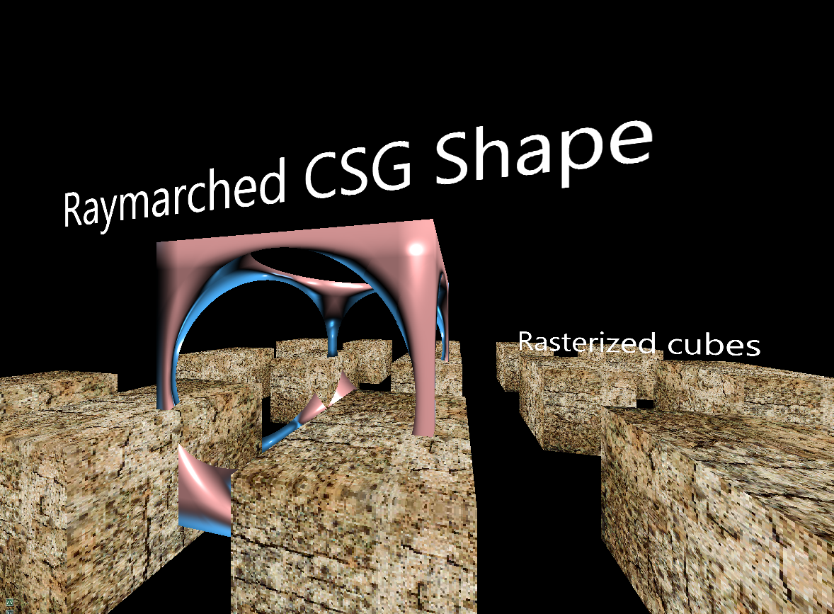
In the opengl-with-luajit sandbox on Bitbucket, I’ve put together a simple example of a hybrid scene combining the 2 rendering types into a coherent output image. The raymarched scene renders first to color and depth buffers, then the rasterized scene renders into the same buffers. The objects in each scene appear to occupy the same space consistently, with nearer objects occluding farther ones.
But does it work in VR?
When implemented correctly it does! Just drop the lua source files from opengl-with-luajit into the lua directory in riftskel. My first attempts at this tried to deconstruct the projection matrix into its constituent components of FOV, aspect ratio and stereo separation, then pass those in as uniforms. From there, attempting to reconstruct the appropriate off-axis projection matrix in shader proved a bit too difficult for me to debug. While I banged my head on this for a couple weeks, a forum post serendipitously appeared, solving all my problems by using the invsrse function in GLSL. Thanks again, Brad Davis!
How does it perform?
Not that I worry too much about it, but a matrix inversion is a somewhat expensive operation that must be performed per-frame. It is called from the fragment shader, does this mean that each invocation of the shader performs the calculation anew? This seems wasteful, if only from a power usage standpoint - in a perfect scenario, the same calculation would be done hundreds of times in parallel, all to arrive at the same result. Assuming it took the same amount of time, it still cost hundreds of times as much power. Plus, the CPU likely operates at a higher frequency and has all kinds of re-ordering capability, so my guess is that the inverse is calculated CPU-side on shader launch by the driver for any shader which is flagged as using the inverse function.
So what do we do with all this?
One application I can think of right now is using the raster pipeline for really tight culling of fragments(pixels) by drawing 3D bounding geometry as “imposters” and calling the expensive raymarching frag shaders only on those pixels we know will be seen.
Unfortunately, all the perfect reflections and refractions that ray-based techniques allow will not “see” the raster geometry we write into the scene(without rendering a cubemap for each reflection point). We could make a game or something with raster objects flying around inside some awesome fractal level geometry, made and stored very cheaply by just a few lines of shader code.
I suspect that there will be some very cool applications discovered in the coming years. There seems to be something of a graphics renaissance happening with developers like paniq and Timothy Lottes at the forefront. They are designing simpler, more efficient techniques that are aimed squarely at exploiting the GPU’s exceptional strengths without paying a high software complexity cost. With features like indirect rendering and compute shaders, maybe it’s not too far-fetched to imagine a world of GPUs frolicking across the countryside, naked and innocent and free from the tyranny of their masters.